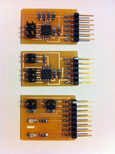
I produced and used 2 standard hello sensor boards this week to gain experience with thermistors and step response sensing.
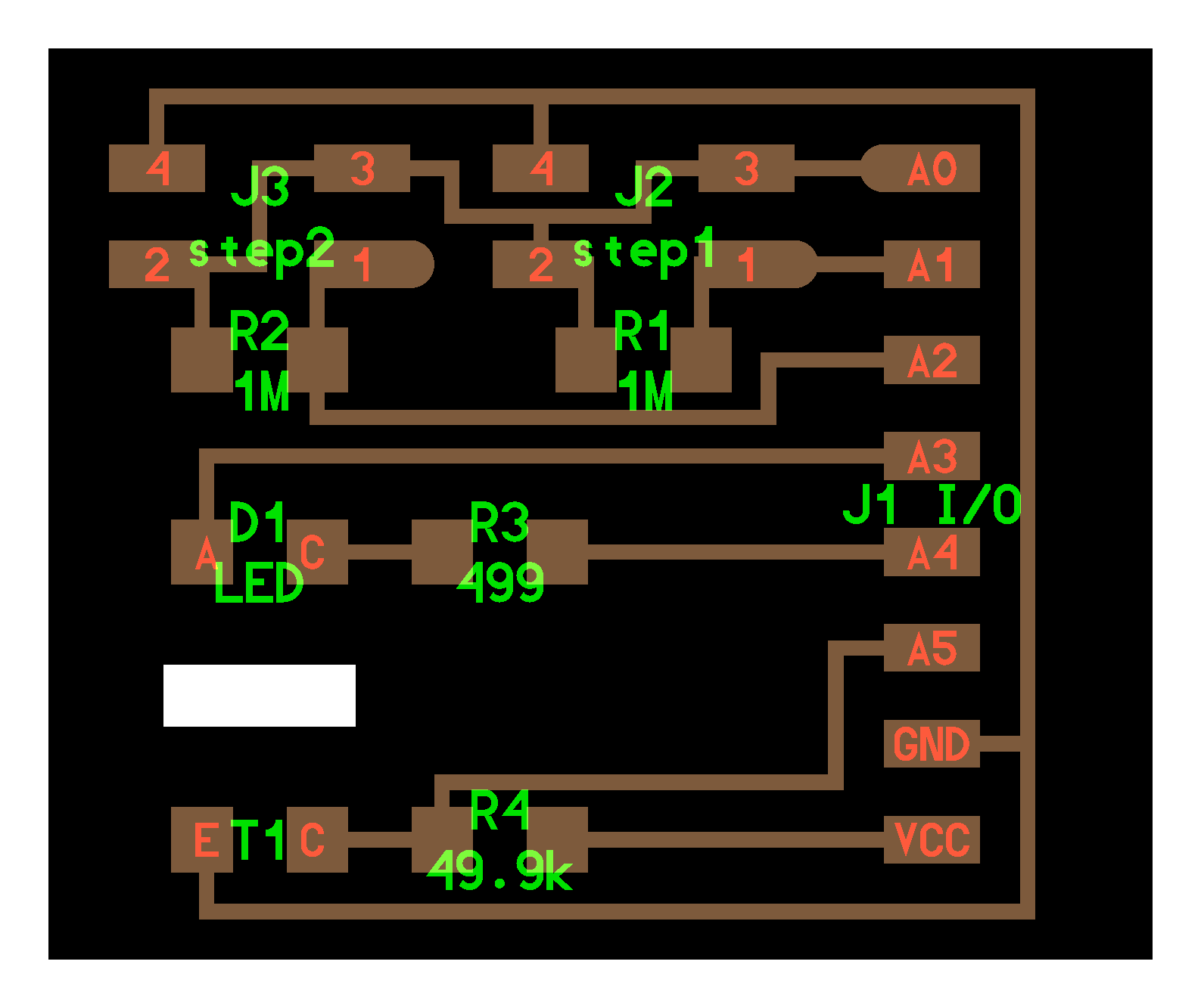
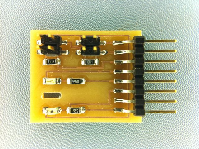
For this weeks project I designed and produced a input board to interface with the FabKit bord that contains 2 step response circuits, a phototransistor for light input and an LED input circuit for light input in addition to output.
Results from compilation and firmware flashing - terminal capture.
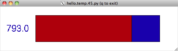
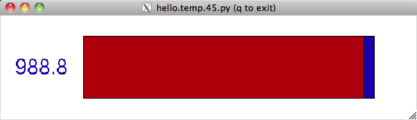
Results from temp measurement host program
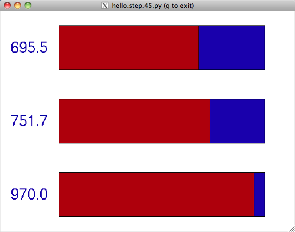
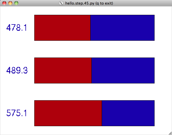
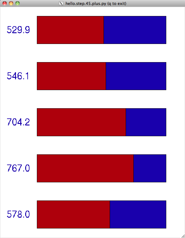
Results from step response host program
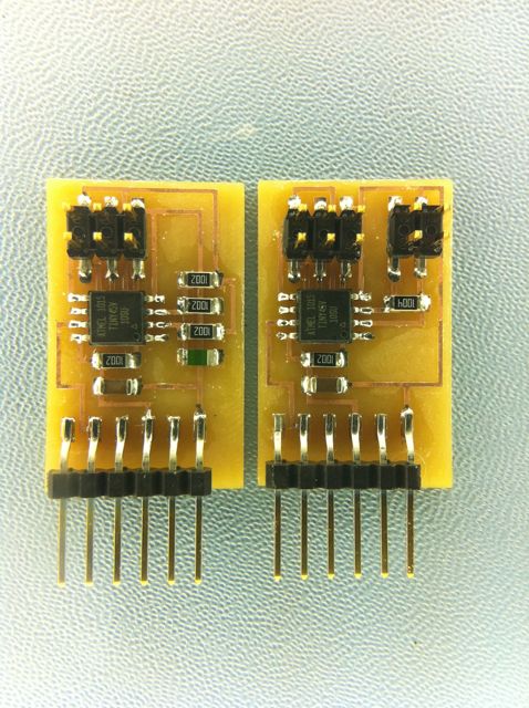
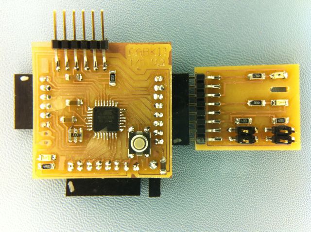
I Constructed a board to plug into the Port C connector on the FabKit board that I produced during the Embedded Programming session.
Port C represents processor port pins that can be used for digital i/o or 6 ADC inputs. The connector represents in Arduino terminology of A0 - A5 and also carries Ground and 5V.
We covered the theory of step and phototransistor input in class. Here is a brief primer on LED input.
The method of using an LED for input involves reverse biasing the junction of the diode (connecting it backward).
The junction then acts as a capacitor holding a charge. The light hitting the LED acts to discharge that capacitor at a rate related the the light intensity.
I connected the LED through a current limiting resistor to 2 processor pins. If the both pins are the same (high or low) the the LED does nothing - no voltage across it.
If the anode is high and the cathode is low it emits light as normal.
If the cathode is high and the anode is low then the junction charges. If the pin connected to the cathode is then changed to an input then the charge on the junction can be measured for input.
Most circuits that I have researched using this technique measure light by measuring the amount of time it takes the voltage of the charged junction to be reduced to a reference level. That creates a variable conversion rate - longer if it is darker.
Instead of keeping the reference voltage constant and measuring discharge time, I chose to keep time constant and measure the voltage after a fixed interval. This maintains a constant conversion rate which is useful for this project.
Look on the web for a lot of information on LED input - Google Search for bidirectional LED.
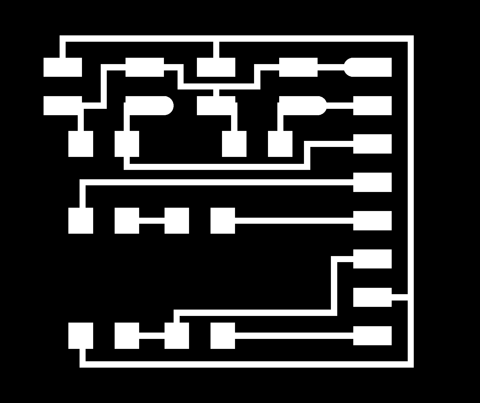
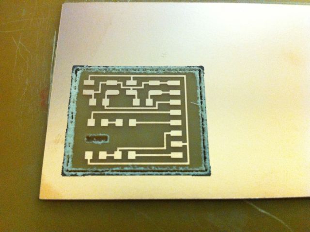
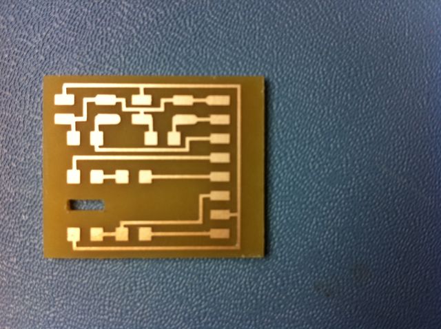
I designed the board using the .cad Hardware Description Language framework. The board also includes a mechanical feature (a slot) for mounting and optical shield HDL (.cad) file of board design.
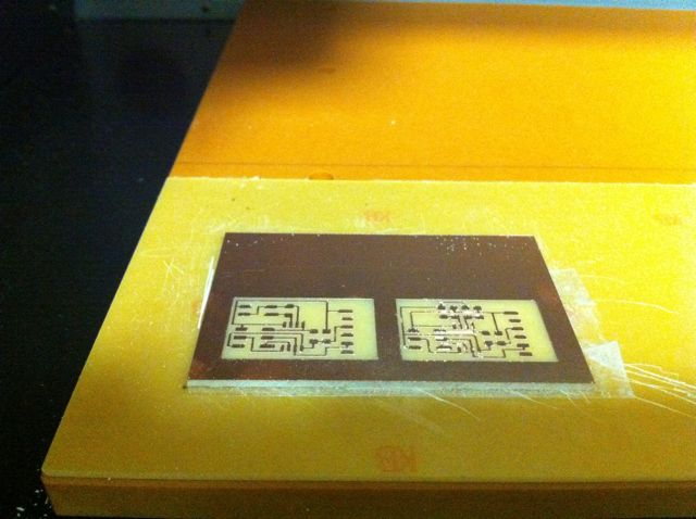
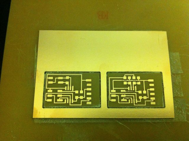
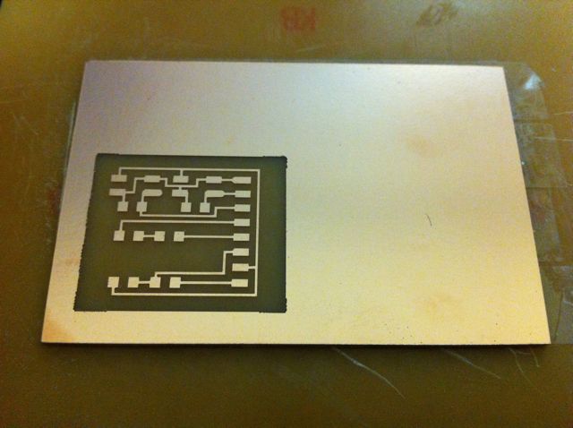
Board production images.
Adapted the step response c program from the class to the arduino environment.
Here is the Arduino based code for the input board.
Adapted the python host code for the hello.step board to
Here is the Python host code for the input board.
Results from input measurement host program.
The boards for this week.